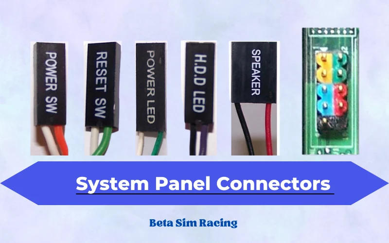
Front panel connectors are needed for all PC users as they can be considered the backbone of the PC case. I know it feels a little stupid that instead of the motherboard, I am saying that panel connectors are the backbone of PCs. Well, if you do not have front panel connectors, how are you supposed to power on your PC, or how will you get to know what is happening inside your motherboard?
Front panel connectors or front panel headers are a block of connectors that control the power on, reset, beep code speaker, and the LED light indicators on the PC. All motherboards contain front panel connectors that connect the motherboard with the pc casing or pc chassis. The cables that connect with the motherboard come from the casings of the PC.
Let me tell you something interesting. These panels consist of small pins that work as specific equipment. All pins connect with their specified switches. The front panel connector is small technical equipment that controls the whole CPU. For example, the two pins of power and reset connected to the motherboard help the user start the computer and pc.
One more thing that the front panel connector does is that it is connected with an LED light system that indicates the CPU’s performance and whether the PC is on or is in sleeping mode. The front panel connectors can jump-start the motherboard. If the power-on button is missing on your PC casing, you can jump-start the motherboard using a precision screwdriver. Touch both power-on switches together, and your motherboard will start working.
What are System Panel Connectors?
System panel connectors are the exact copy of a front panel connector. The only difference between this technical equipment is their names. Otherwise, they perform the same functions. I was nervous when I began learning about technological assets, but after some time, I realized that these two are similar things with different names.

Functions of Front Panel Connectors
There are five primary functions that a front panel connector performs.
- Helps in switching on the CPU
- Indicates the performance of the CPU
- Beeps to tell the problems of the cpu
- Indicates when the CPU is in reset mode
- Indicates the performance of the hard drive by a continuous flash
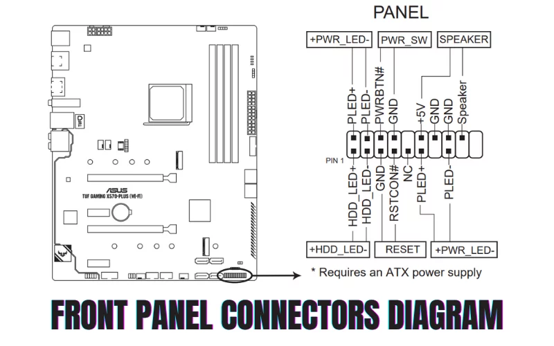
What is Front Panel Connectors Diagram?
These computer panel connectors were science in starting, but now they have become relatively easy to install. The user only follows the manual and can connect their motherboard front panels, but some still do not understand it, so let me explain it to you.

This front panel connector comprises PLED +- switches on the top left. This indicates whether the PC is powered on or in sleep mode. The three switches on the top right are the pins of internal motherboard speakers that tell the modes and performance of the CPU by beeping. The IDE_LED +- switches on the bottom left indicate the performance of your hardware drive.
Whereas the PWRSW pins present in the bottom middle of the front panel connectors are the switches that control the button that is used to turn on and off your PC. And in the end, the two switches at the bottom right of the panel are the reset switch.
Types of Front Panel Pins on Motherboard
There are five essential functions and the pins on the motherboard concerning them. Following is the description of the front panel pins on the motherboard.
- Power Switch Pins: PWRSW or PW are two pins that connect the Power button cable with the power switch that controls the PC’s power on and off function.
- Reset Switch Pins: These two pins connect the reset switch with the reset cable on the chassis of your PC.
- Power LED Pins: Also known as PLED pins, these three pins connect the LED light on the PC case with the motherboard. These LED lights indicate whether the PC is on, off, or in sleep mode.
- Hard Disk LED Pins: he two pins connect with LED lights that indicate the activity of the hard disk by flashing continuously.
- Speaker Pins: These are the 4 pins connected with internal motherboard speakers or beep code speakers on the PC casing. It helps in identifying and troubleshooting any hardware issues faced by your PC.
What are Front Panel Cables?
Once I had a great experience while working with my father. I got some serious issues with my PC as it was not working as per my expectation, so I asked him to take a look at it. And guess what? He decided to look at the front panel connector and motherboard. My new CPU was not working correctly because some cables on the front panel were not in place. At that moment, I realized that these cables are worth using if placed correctly. Now let me tell you a little info about them.
The system panel cables are not keyed so that they can be placed in any direction. In modern-day motherboards, front panel connectors + and – signs are labeled, making it easy for users to connect them. The labeled motherboard shows the directions of the cables.
Front Panel Connectors Adapters
The front panel connector adapters are the devices that are connected to all cables and pins on the PC. It allows the user to plug the cables with the pins on the panel connectors present on the motherboard. These adapters have different capabilities and ranges concerning pins and cables.
Sometimes, when some front panels miss any specific pin, the adaptor would be needed as per demand. These USB adaptors are easy to use. The King win power USB adapter is a 3.0 type adapter that supports all SATA types of drives. They can easily connect with WIN/2000/VISTA/7 MAC etc.
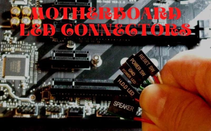
What are Motherboard LED Connectors?
The motherboard LED connector is the PLED light on the PC casing. Two PLED connectors are labeled PLED 1 and PLED 2, indicating the computer’s mode, whether the PC is on, off, or in sleep mode. These connectors, while connected, should be placed in their respective directions; otherwise, the LED lights will not work.

ASUS Motherboard Front Panel Connectors
ASUS motherboards are efficient motherboards that are superb in all performance, either in professional fields or in the gaming field. All wanted them. So, their front panel connectors also gain the attention of many people. Mostly ASUS motherboards are fun to install.
The outstanding installation of front panel connectors in this motherboard is an exciting process. I have not installed any front header connectors in this motherboard alone but watching others do it was an exciting experience.
Let me specifically tell you about the front panel connectors of the ASUS B550 series. In this series, all motherboards are supported by AMD Ryzen 5000 and 3000 series. The front header connectors of the B550 series mostly contain USB 3.2 Gen 2 support and are pre-mounted with an I/O shield. Some B550 motherboards support USB 2.0 front panel headers. These front panel headers mainly support USB C type.
Front Panel Connectors Gigabyte Motherboards
Gigabyte motherboards have a unique feature of a G connector. It can connect all the tiny front panel connectors at once. It will be easy and convenient for every PC builder because it will save you time, and you will not be fed up with connecting many wires.
Following are some motherboards that contain USB 3.2 front panel connectors:
- B550-E Gaming
- B550-I Gaming
- ASUS Optimum II
- B550M Plus
B550-E Gaming Motherboard
The ASUS B550-E Gaming motherboard has 1 USB 3.2 Gen 2 with 2 front panel connectors. The front panel audio header is attached with a PC casing and consists of 4 pins. The system power header supports several functions, including 2-pins PWR-LED, 2-pin HDD-LED, 2-pin PWR button, and 2-pin Reset button.
Interesting Fact:
Let me tell you something if you find any colored cable in your front panel, they are known as power cables that connect with the + terminal, whereas the black or white cable is known as the round cable that connects with the – terminal.
Let’s take the example of PLED pins and their cables. The 1st pin of PLED is labeled as PLED+, indicating that a colored or power cable will connect with it. While the 2nd pin that is labeled with PLED- indicates that the ground cable will relate to it.
The computer front panel connectors are essential to computer hardware as they connect the basic CPU hardware with the motherboard. They not only control the performance of the PC by controlling the motherboard but also keep a complete check of the hardware performance. It indicates the modes and problems of the motherboard and hard disks, and if not connected correctly, it can give a lousy performance to the whole motherboard.
Conclusion


1 Comment
Can you be more specific about the content of your article? After reading it, I still have some doubts. Hope you can help me.